Are you looking to test your motherboard but don’t have access to specialized equipment? Did you know that you can use a multimeter to test the various components of your motherboard? It’s a handy tool that can help detect any faults and identify potential issues. In this article, we’ll explore how to test your motherboard using a multimeter. We’ll discuss the key components that you should test, the tools you’ll need, and the steps you should follow.
Whether you’re a seasoned computer technician or a novice DIY enthusiast, this guide will provide you with the knowledge you need to ensure the smooth operation of your motherboard. So, let’s get started!
Gathering Tools and Preparing Motherboard
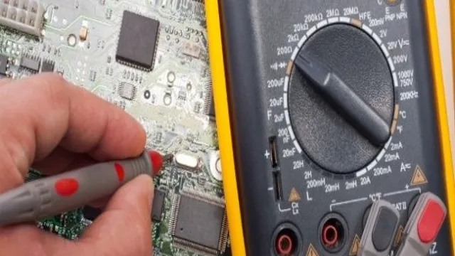
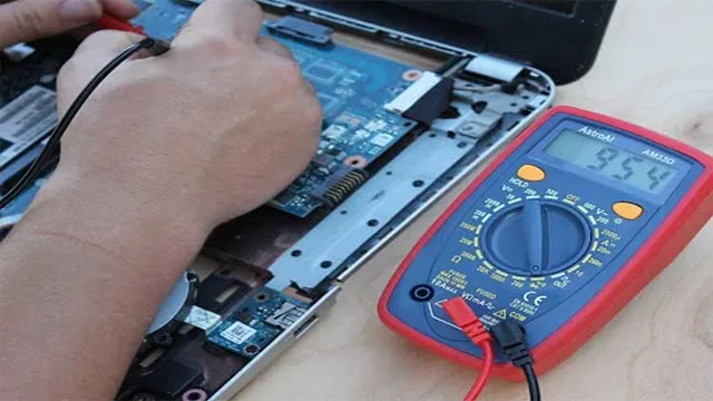
If you’re looking to test a motherboard with a multimeter, it’s important to gather the right tools and take the necessary precautions before diving in. First, make sure you have a reliable multimeter that can measure DC voltage, resistance, and continuity. You’ll also need a set of small screwdrivers and a grounding strap to protect the motherboard from static electricity.
Once you have all your tools in hand, you can begin preparing the motherboard by removing it from the computer and disconnecting all peripherals and cords. Take note of any visible damage or corrosion on the motherboard, as this may affect your testing results. Before testing any components, be sure to discharge any residual electricity from the motherboard by holding down the power button for a few seconds with the power cord disconnected.
Following these steps can help ensure a smooth and accurate motherboard testing process.
Checking for Power Supply Issues
If you’ve been experiencing power-related issues on your computer, the first thing you should do is check your power supply unit (PSU). But before you start tackling the PSU, make sure to gather the necessary tools and prepare the motherboard first. You’ll need a screwdriver to remove the screws securing the PC case, as well as a grounding wrist strap to ensure you’re not statically charged.
Once you’ve opened the case and exposed the motherboard, take note of the PSU’s location, which is usually at the top or bottom. Now, unplug all cables connected to your motherboard, PSU, and other components like hard drives, graphics card, and RAM. Doing this will prevent any electrical discharge that might harm any hardware.
Once you’ve disconnected everything, follow the PSU’s manual and remove it from the case. From there, you can start examining it for any visible damages like bulging capacitors or burnt marks. If the PSU looks fine, you can jumpstart it using the Paper Clip Test to see if it’s working correctly.
Remember never to open a PSU’s case as it contains dangerous voltages that can harm you. Always wear protective gear and follow proper procedures when working with PSUs. Overall, checking for power supply issues can be a bit complicated, but with the right tools and knowledge, you can rule out any potential problems that might affect your computer’s performance and stability.
Identifying Proper Voltage Readings
When it comes to identifying proper voltage readings on a motherboard, it’s important to gather your tools and prepare the motherboard before jumping in. First and foremost, you’ll need a multimeter, a small flathead screwdriver, and some thermal paste. Once you have these tools at the ready, carefully remove your motherboard from its case and place it on a static-safe surface.
Take note of the various voltage points on the motherboard, paying close attention to the CPU and power supply. Using your multimeter, test the voltage at each point and compare it to the expected ranges outlined in your motherboard’s documentation. If you notice any deviations from these ranges, it’s important to troubleshoot the issue before continuing with your build.
By taking the time to properly prepare your motherboard and gather your tools, you’ll be well on your way to identifying any voltage issues and ensuring a smooth and stable build.
Testing Specific Components
If you’re looking to test a motherboard with a multimeter, there are a few specific components that you’ll want to focus on. One of the most important components to check is the power supply section. You can check this by measuring the voltage outputs on the ATX power connector with your multimeter.
If the voltage is within the acceptable range, you can move on to testing other components like the RAM, CPU, and chipset. To test the RAM, you can use a memory testing program like Memtest to check for any errors. For the CPU and chipset, you can use a stress testing program like Prime95 to ensure that they are functioning properly under load.
Finally, you’ll want to test the motherboard’s BIOS by checking for any error codes or messages during the boot process. By testing these specific components, you can ensure that your motherboard is functioning properly and identify any potential issues before they cause serious problems.
Testing RAM Modules
When it comes to computer troubleshooting, one of the common issues a user might encounter is a faulty RAM module. Random Access Memory (RAM) is an essential component in any computer system, as it temporarily stores data that the system needs to run programs and perform tasks. If your computer system is lagging or experiencing random crashes, it might be due to a bad RAM module.
The first step in troubleshooting this issue is to run a RAM diagnostic test to determine whether your RAM modules are functioning properly. There are various RAM diagnostic tools available that can help identify issues with your RAM, such as MemTest86 and Windows Memory Diagnostic. These tools can detect any errors or problems with your RAM and provide troubleshooting advice to rectify the issues.
By testing your RAM periodically, you can ensure that your computer system runs more smoothly and efficiently.
Testing CPU and Socket Connections
“Testing CPU and Socket Connections” When it comes to building or repairing a computer, one of the most important tasks is ensuring that the CPU and socket connections are functioning properly. This can be a daunting task for those who are new to computer hardware, but with a little bit of knowledge and practice, it can be done with ease. To test the CPU, you’ll need to use a program like Prime95 that stresses the processor to its maximum potential.
This will help identify any issues with overclocking, overheating, or instability. To test the socket connections, you’ll need to visually inspect the pins or contacts on the CPU and socket to ensure that they are clean and free of damage. If there are any bent or broken pins, they will need to be carefully straightened or replaced before testing can begin.
Once everything is in order, you can test the socket connections by booting up the computer and monitoring the CPU temperature and system stability. With these simple steps, you can ensure that your computer is running smoothly and efficiently.
Testing Capacitors and Transistors
Testing capacitors and transistors is a crucial aspect of electronic repair work. Capacitors and transistors are common components that can become faulty and prevent electronic devices from working properly. Therefore, it’s important to troubleshoot and test these components when diagnosing problems.
When testing capacitors, a commonly used method is to measure the capacitance using a digital multimeter. Additionally, a capacitor tester can be used to quickly determine the capacitance and allow for in-circuit testing. When testing transistors, a multimeter can be used to measure the voltage drop across the base-emitter junction.
With this voltage reading, one can determine whether the transistor is working properly or not. It’s important to note that testing these components requires knowledge and experience in electronics repair, so it’s always best to consult a professional if unsure.
Interpreting Multimeter Readings
When it comes to testing a motherboard using a multimeter, it’s essential to understand how to interpret the readings correctly. The first step is to gather all the necessary tools, including the multimeter, a user manual, and a set of probes. Next, locate the various voltage points on the motherboard, such as the CPU voltage regulator circuit, the system bus, and the power supply connector.
Set the multimeter to the appropriate voltage range and use the probes to measure the voltage at each point. A reading within the expected range indicates that the particular component or circuit is functioning correctly, while a value outside the normal range may indicate a problem that requires further investigation. Remember to consult the user manual for the motherboard and multimeter for specific instructions and recommended voltage ranges.
By following the necessary steps and interpreting the multimeter readings correctly, you can identify and diagnose any issues with your motherboard with ease. Thus, testing a motherboard with a multimeter is an effective way to ensure its proper functioning and avoid significant problems in the future.
Understanding Ohm’s Law and Resistance
When using a multimeter to measure resistance, it’s essential to understand the readings that the device provides. The most crucial aspect of measuring resistance is Ohm’s Law, which tells us that the current flowing through a conductor is directly proportional to the voltage applied across it. Therefore, when using a multimeter to measure resistance, we must adjust the device to measure voltage first.
Once we have the voltage reading, we can divide it by the current reading to find the resistance. We can also use the ohmmeter function on some multimeters, which measures resistance directly. It’s important to note that the resistance of a conductor can depend on various factors, such as temperature and material.
Therefore, it’s crucial to have a good understanding of the material you’re working with to interpret the multimeter readings accurately. In summary, mastering the interpretation of multimeter readings requires a good understanding of Ohm’s Law and the properties of the conductor you’re measuring.
Analyzing Voltage and Amperage Readings
When working with electrical equipment, it’s important to have a basic understanding of how to interpret the readings on a multimeter. Two of the most common readings you’ll come across are voltage and amperage. Voltage refers to the electrical potential difference between two points in a circuit and is measured in volts.
Amperage, or current, refers to the flow of electric charge and is measured in amperes. By measuring these two values, you can determine if a circuit is working properly or if there’s a problem that needs to be addressed. For example, if the voltage reading is too low, it could indicate a problem with the power source or a component in the circuit.
Conversely, if the amperage reading is too high, it could mean that there’s a short circuit or a problem with a particular component in the circuit. By understanding how to interpret voltage and amperage readings, you’ll be better equipped to troubleshoot and identify issues with electrical systems.
Conclusion and Follow-Up Steps
So, there you have it! Testing a motherboard with a multimeter is not rocket science, but it may require some patience and knowledge of electrical current. As with any DIY project, it’s important to follow the correct procedures and be extra careful when dealing with electricity. With these tips, you should be able to diagnose and fix any issues with your motherboard, and have your computer up and running in no time.
Plus, now you can impress your friends by showing off your mad multimeter skills. Happy testing!”
FAQs
What tools do I need to test a motherboard with a multimeter?
To test a motherboard with a multimeter, you will need a multimeter, an antistatic wrist strap, and a motherboard manual or diagram.
How can I use a multimeter to test if my motherboard is getting power?
Set your multimeter to measure voltage, and then connect the positive probe to the motherboard’s power supply connector and the negative probe to a ground point. If the voltage reading matches the required specifications in your motherboard manual, then your motherboard is receiving power.
Can I use a multimeter to test if my motherboard is short-circuiting?
Yes, you can. Set your multimeter to measure resistance, and then connect the positive and negative probes to different pairs of motherboard pins or connectors. If you receive a reading of 0 ohms or a very low resistance, then your motherboard may be short-circuiting.
How can I use a multimeter to check if a component on my motherboard is faulty?
Set your multimeter to measure continuity, and then connect the positive and negative probes to the component you want to check. If there is continuity (i.e., the multimeter beeps), then the component is functioning correctly. If there is no continuity, then the component may be faulty.